Gas insulated LBS/Sectionalizer
Description
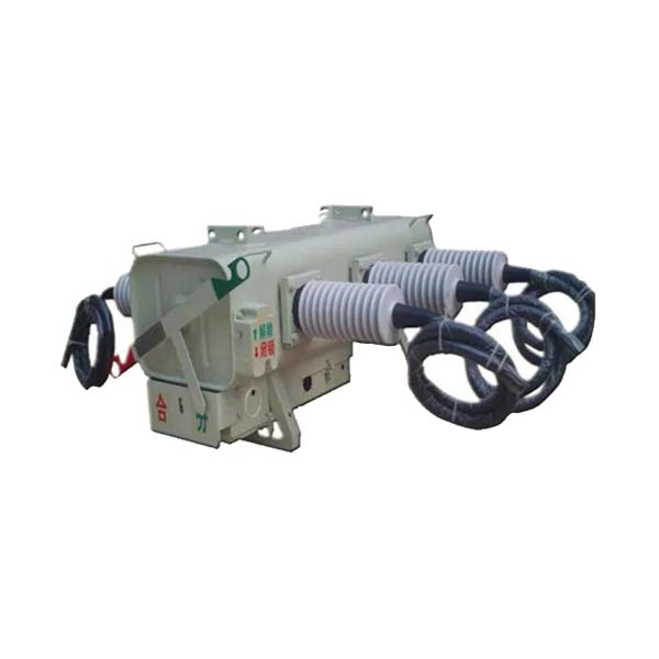
RPS type Pole-mounted load-break switch (pole-LBS) is a protective device for protecting power distribution system. It usually combines with automatic circuit reclosers (acr). It applies up to 36kV 400/630A, 50Hz pole-LBS associated with a smart sectionalizer controller. This is SF6 gas-insulated switch can corporate with the distribution automation system, and also isolate a faulted section of distribution line from the control center.
It is a simple pole-mounting arrangement contribute to quick and low cost installation, and the switch can be operated manually with a smart sectionalizer controller.
The smart controller is contained in a stainless steel cabinet for an all weather environmental conditions. Remote monitoring and control can also be provided mounting wire or wireless Modem in a cabinet.
Standard servicecondition
It shall be principal that this SF6 Gas Load Break Switch (Sectionalizer) shall be used in the following service condition;
Ambient temperature
Short period peak value: 50℃ average
Over a period of 24 hours: 40℃ lower
Limit over 24 hours: -25℃ relative
Humidity: 100%
Maximum altitude: 1000 meter
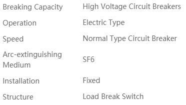
Features
SF6 Gas Insulation
SF6 gas is a nontoxic, non-flame-able dielectric with excellent arc quenching property.
Bushing Versatility
In addition to the standard porcelain bushing, a variety of options are available including elastomeric insulator over epoxy apparatusbushing.
Visible Open/Close
The color coded main contact position indicator(green-open, red-closed) is easily visible from the ground. the indicator is connected directly to the main contact drive shaftass embly assuring accurate contactsstatus.
Quick Operation
Spring charged operator is being utilized compression spring to assure quick make and quick-break operation.
Remote controllable
Electronic controller is available offering local operation or RTU-interface for masterstation control.
Robust Switch
The switch is manufactured from robust, corrosion resistant, proven materials to ensure long service life and also capable of an number of operations which is an ideal characteristic for pole-mounted equipment.
Standard
Every switch is factory filled, hermetically sealed and production tested according to IEC 60265-1(1988) prior to shipment.
Technical data
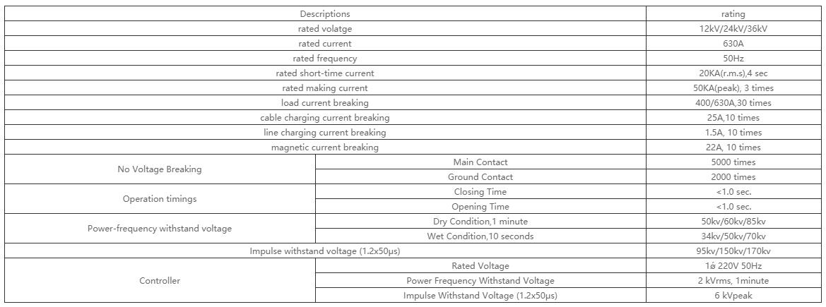
Types and Ratings
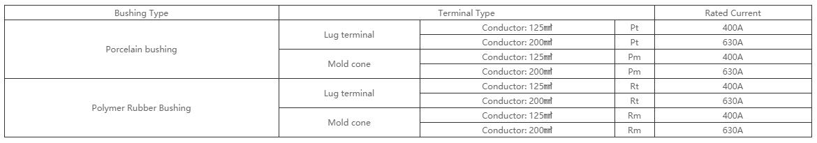
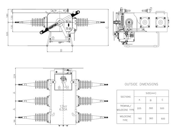
Note:Clearance copper terminal without cable section is 240 mm2
Types of LBS
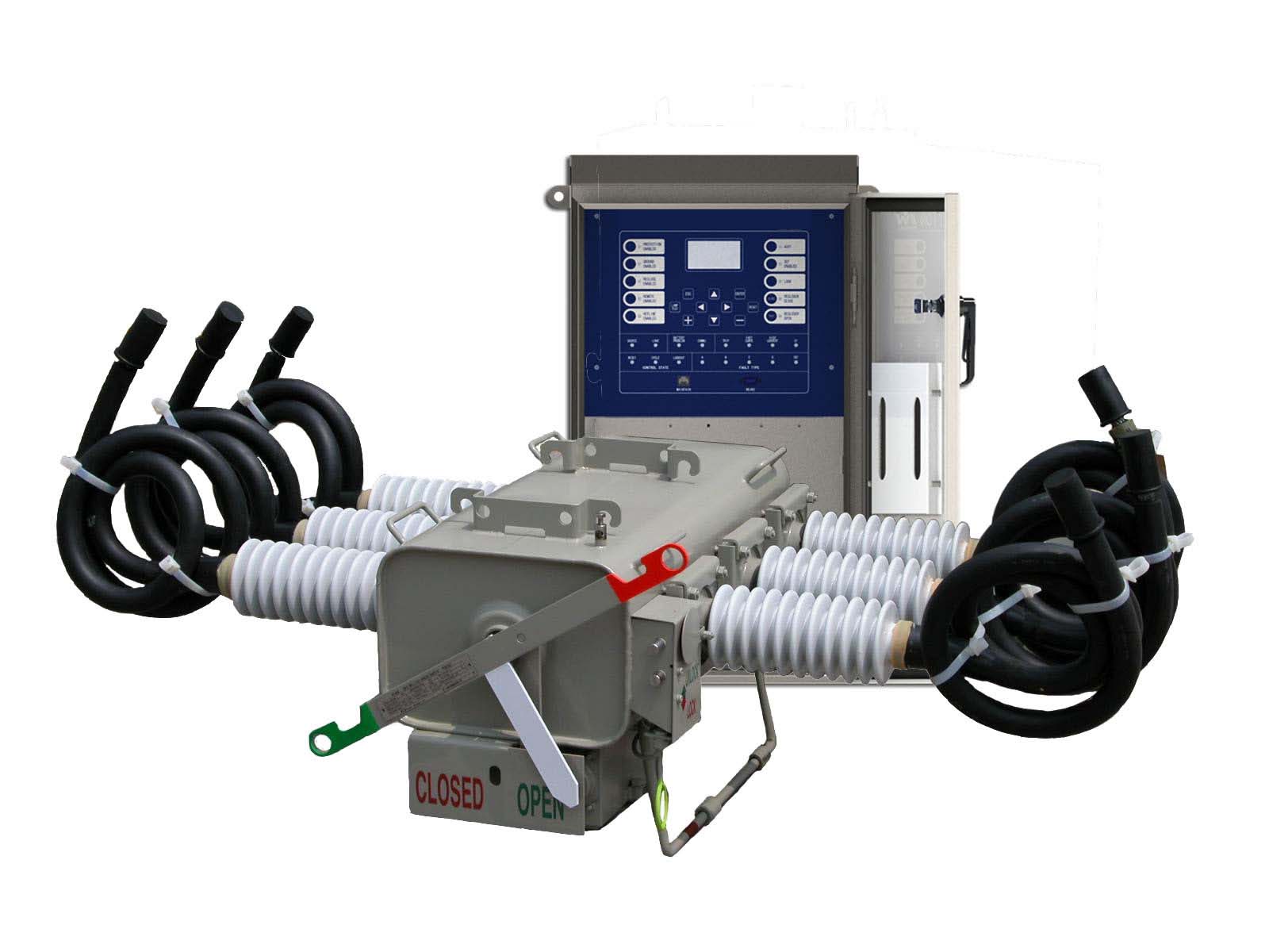
Fig.1) Porcelain Bushing – Mold Cone
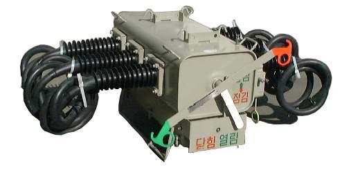
Fig.2) Rubber Bushing – Mold Cone
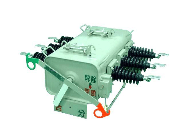
Fig.3) Rubber Bushing – Lug Terminal
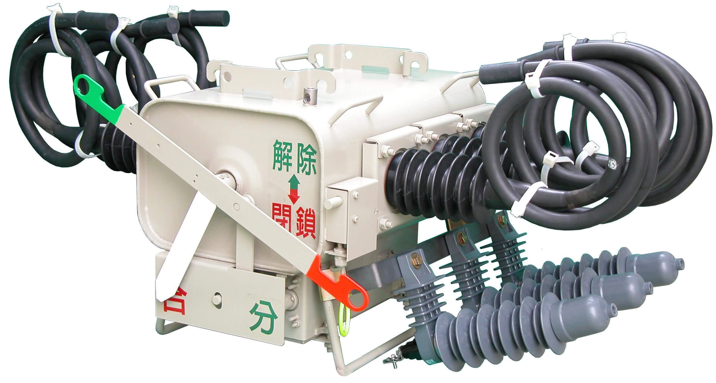
Fig.4) LBS with Surge Arrester
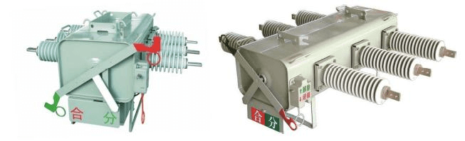
Fig.5) porcelain Bushing
Construction
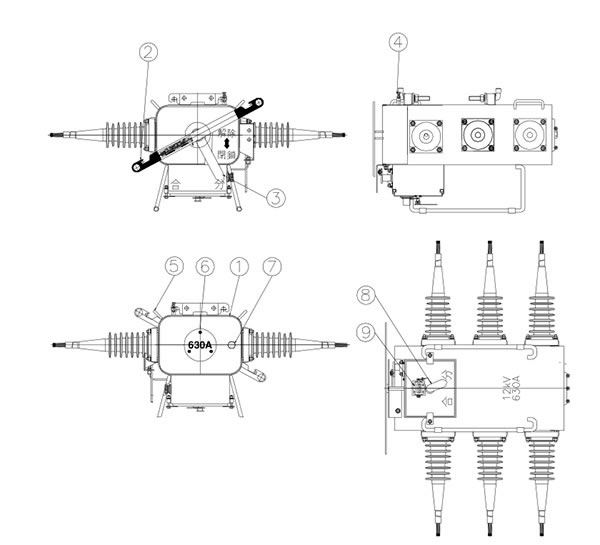
1.Trip handle;2.Operating handle;3.Indicator;4.Earth terminal;5.Lighting lug;6.Safty-protection cover;7.Gas filling value;8.Indicator;9.Operating COUNTER
LBS Main Body
SF6 gas insulated switch is a three-phase gang-operation switching device designed for cable and overhead line sectionalizing applications on distribution systems, being operated manually at site or remotely from control center.Switch tank shall completely sealed by welding and/or rubber -seal gasket, and all components shall be assembled in a welded stainless steel tank.Switch tank shall be designed to withstand internal pressure without affecting the performance ofthe switch. The enclosure of tank is used of the material of the cold rolling stainless steel of over 3mm (STS304L) or more than equivalent to be able to endure against inner gas pressure and is treated for completely anticorrosive by coating of resin over the enclosure.And the enclosure is the rustless structure by separating bottom side over 10 mm from ground.
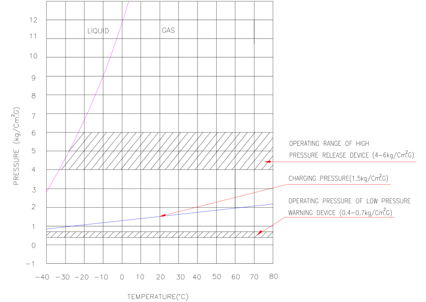
Fig. 6) Temperature-pressure characteristic curve
SF6 gas used for Pole-LBS is high-pure products and is designed and manufactured to keep below 1,000ppm for water content in gas of main body during loaded current switching.Considering application temperature range and gas leakage of gas in Pole-LBS, rated pressure,maximum pressure, maximum guaranteed pressure and gas pressure drop locking pressure are asshown in attached
The factory built-in accessories
Manual operating handle
The LBS is to be safely and easily operated by hot stick for high voltage, and is the structure being completed the on or off by one time operation.
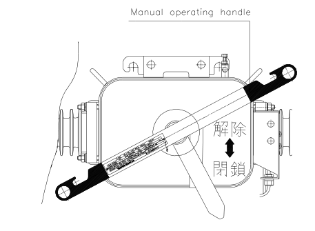
Dwg.1) Manual operating handle
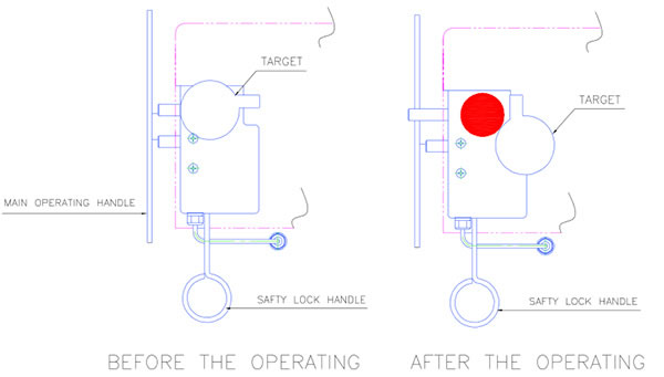
Safety lock device
It is possible to lock the operation apparatus in the position of On or Off, its structure is impossible to electrically and mechanically operate to on or off position in case of locking.
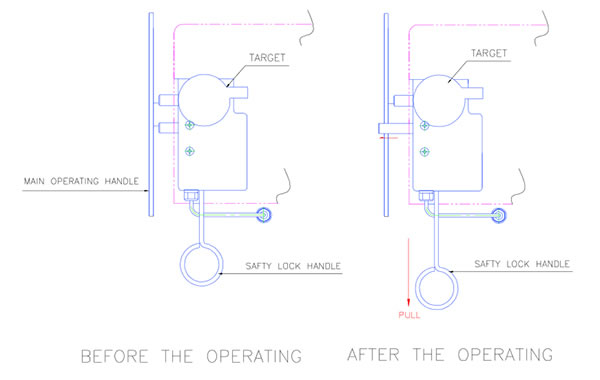
Dwg.2) Safety lock device
Contact position Indicator
The color coded main contact position indicator(green-open, red-closed) is easily visible from the ground
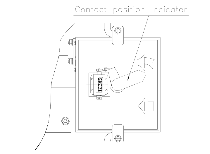
Dwg.3) Contact position Indicator
Low pressure warning device
The automatic locking apparatus is equipped to be impossible for electrical and mechanical On-Off operation in the state of causing a risk when On-Off operation due to the pressure drop(0.4~0.7 ㎏/㎠.G) and there is the indicator being able to easily certify by the operator
Dwg.4) Low pressure warning device
High pressure release device
The gas release apparatus with the structure preventing the demolition of the tank for the safe of operator and common people and that the inner apparatus is not spread to outside in case of sudden rising of the inner gas pressure of the main body due to the internal trouble is equipped.
Dwg.5) High pressure release device
Gas filling valve
The valve is equipped to instill gas in the tank of the main body
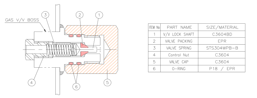
Dwg.6) Gas filling valve
Grounding Terminal
Its structure is easily connect with the copper cable of 22mm² ~ 38mm² without the extra auxiliary clamp
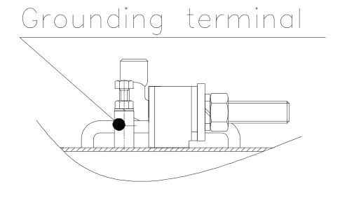
Dwg.7) Grounding terminal
Lifting lug
The four (4) Handle for transportation are installed on the upper side of the main body
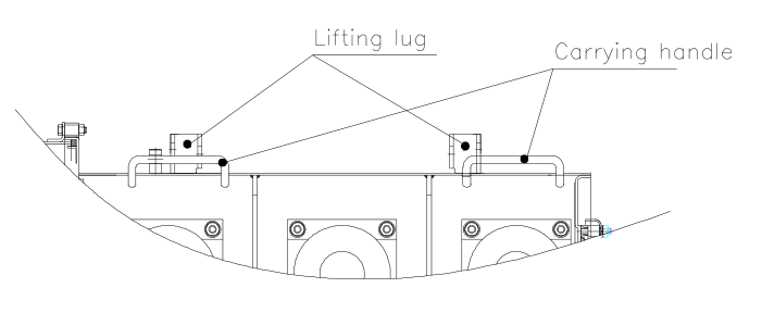
Dwg.8) Lifting lug
Polymer Rubber Bushing
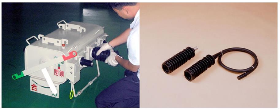
Fig.7) Rubber bushing Fig.8) Rubber Terminal & Rubber Mold-cone
The material of the bushings is as of the epoxy and EPDM rubber or porcelain.
Features of the epoxy and EPDM rubber
- Light weight and easy to handle.
- Unbreakable.
- Integrated design with moldcone.
- Excellent Mechanical Strength.
- Self cleaning function.
- Short installation time and maintenance.
External connection terminal
The insulated cable for high voltage that has the flexibility and weather proof for the mold conelead wire method is used, the nominal area and composition of core are over 125 ㎟(159/1.0) for 400A and over 200 ㎟(19/14/1.0) for 630A, and the length required is over 2m.In case of the terminal type, allowable current for sectional area of the conductor is 630A.
Operating
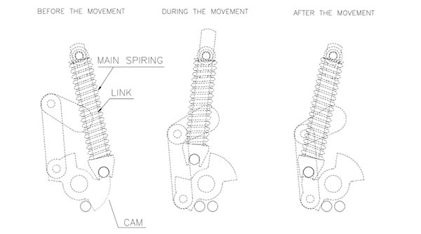
Dwg.9) Operating Mechanism
LBS Controller
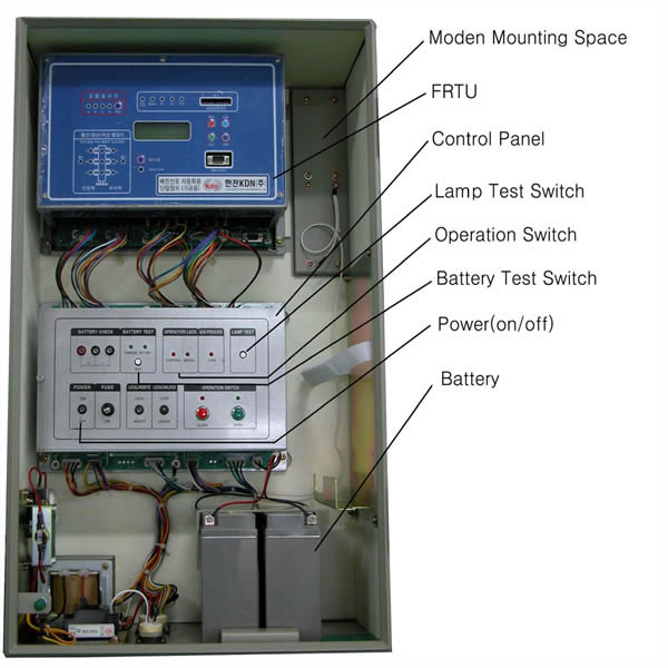
The control box shall be manufactured by using stainless steel plate over than 1.5mm thickness and shall have the installing clamps to easily install at the concrete pole;The controller can operate the pole-LBS by locally or remotely;The controller monitors the SF6 gas pressure of pole-LBS.If gas pressure falls below a pre-set threshold(0.4-0.7kg/㎠.G), then an SF6 low pressure red lamp is lit on the local panel, and electrical and manual operations are locked out. The control box contains the following operation and display device
Operation switch: Close, Open
Operation selecting switch: local/remote
Operation locking switch: Lock/unlock
Rechargeable battery test terminal and test switch
Lamp test switch
Control power switch (on/off) and fuse
LED
- Display of main contact condition: close(red), open(green)
- Display of locking for low gas pressure
- Display of locking for switching operation (Control box/main
body)
- Display of condition of recharging part and rechargeable battery
The rechargeable batter and charging devices are as follows Rechargeable battery for control power
- This is DC 24V and rechargeable. This makes more than 50 switching operations by just recharging once and contains the rechargeable battery, which has capability that lasts more than 24hour control under failure of AC power.
Rechargeable battery and charging device
- The recharging current necessary for the battery by ambient temperature is controlled automatically. It contains protection circuit from the over-charge and over-discharge. Test terminal of rechargeable battery
- Terminal for test and the display of charge condition of article are equipped so that the conditions of the battery voltage and of the charging device can be checked under loading/unloadin
condition.
Connecting diagram
Dwg.10) Connecting diagram on the lug terminal
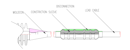
Type #1) Insulation Piercing Connector
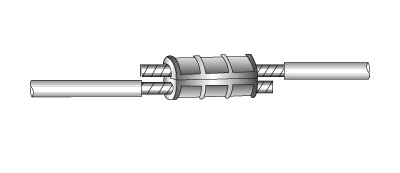
Type #2) Compression Sleeve
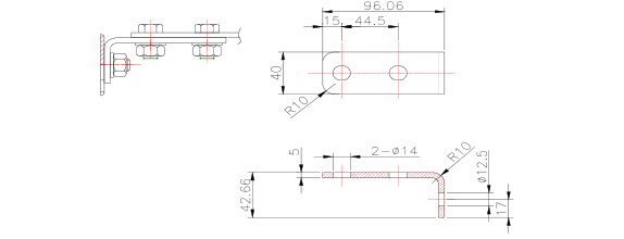
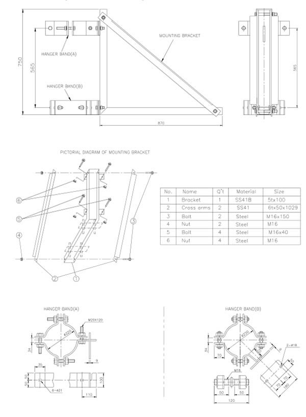
Detail drawing for Pole Mounting Bracket
Connection of the cable to the switchgear
Switch Mounting and Dimensions (Automatic Type)
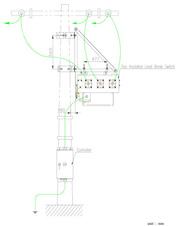
Dwg.11) Switch Mounting and Dimensions
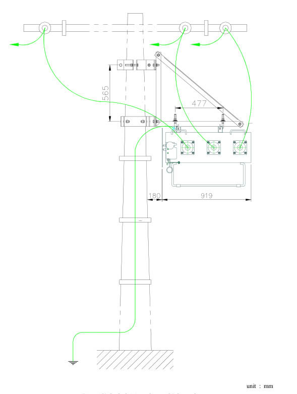
Dwg.12) Switch Mounting and Dimensions
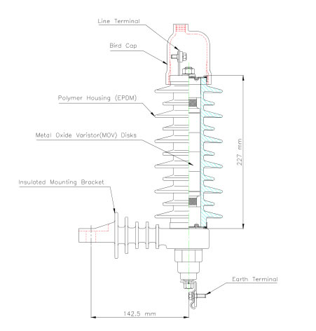
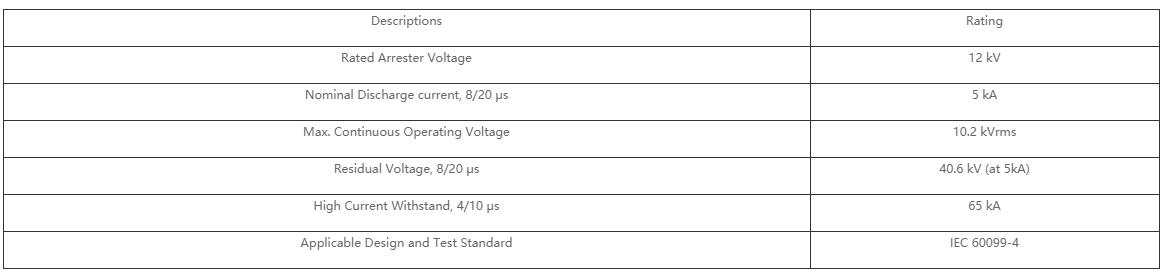
Surge Arrester
Overview and Dimension

Address: NO.308 WEI 17 RD CENTER INDUSTRIAL PARK YUEQING CITY ZHEJIANG CHINA 325600
Tel: 0086-577-62667968
Phone: 0086-13868723687
E-mail:Sales@dist-transformer.com
Scan the code to browse the official website of the mobile phone


