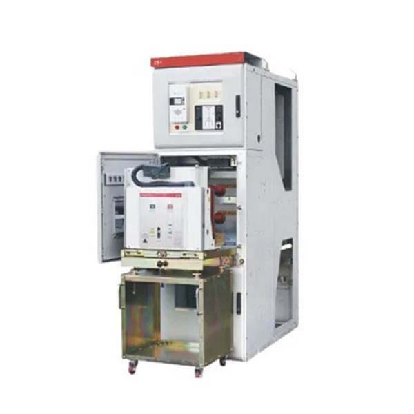
Description
China KYN28 indoor metal-clad withdrawable switchgear(hereinafter short as switchgear)is a complete power distribution device for 3.6~24kV,3-phase AC 50Hz,single-bus and single-bus sectionalized system. It is mainly used for power transmission of middle/small generators in power plants; power receiving, transmission for substations in power distribution and power system of factories, mines and enterprises, and starting of large high-voltage motor, etc.,so as to control,protect and monitor the system. The switchgear meets IEC298,GB3906-91.In addition to be used with domestic VS1 vacuum circuit breaker, it can also be used with VD4 from ABB,3AH5 from Siemens domestic ZN65A,and VB2 from GE, etc.,it is truly a power distribution device with good performance. In order to meet the requirement for wall mounting and front-end maintenance, the switchgear is equipped with a special current transformer, so that the operator can maintain and inspect it in front of the cubicle.
a. Ambient temperature: Maximum temperature:+40℃ Minimum temperature: -15℃
b. Ambient humidity: Daily average RH no more than 95%;Monthly average RH no more than 90%
c. Altitude no higher than 2500m;
d. The air around without any pollution of duty,smoke,ercode or flammable air,steam or salty fog;
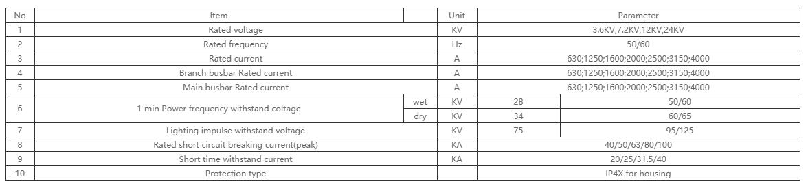
Technical data
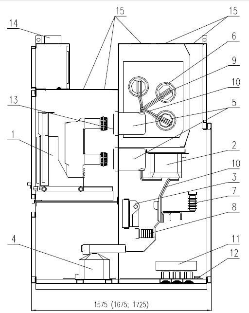
Structure & Basic Components of Switchgear
Structure & Basic Components of Switchgear
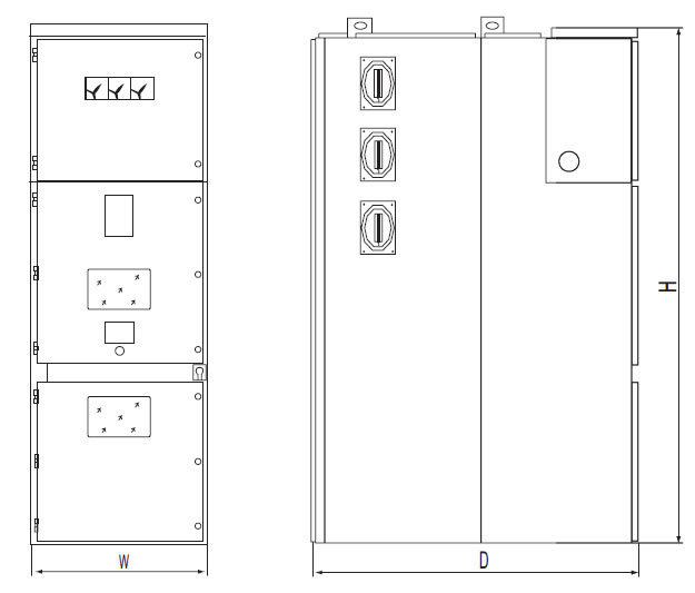
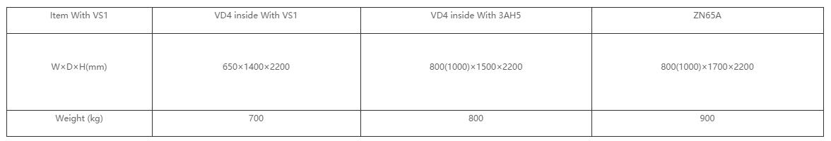
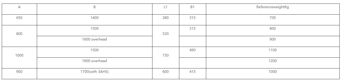
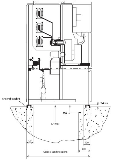
Overall size and weight
Notice:
when the rated current is more than 1600A, cubicle width shall de 1000 mm, and cubicle height will be 1660mm and for schema of rear overhead line in.
1)Width of cabinet:650mm(compound insulation)or 800mm(air insulation) at current<1250A;
2)Width of cabinet:1000mm at current>1250A;
3)Depth of cabinet:1400mm,at cabinet width of 650mm(compoud insulation)when employing theconfiguration of incoming and outgoing cables;
4)Depth of cabinet:1500mm,at cabinet width of 6800mm(air insulation)when employing theconfiguration of incoming and outgoing cables;
5)Depth of cabinet:1600mm,when employing the configuration of rear overhead incoming andoutgoing cables.
Structure Features
1) compartment
busbar compartment; circuit breaker compartment; cable compartment; low-voltage compartment.
1 - main device: circuit breaker, contactor,
2 - current transformers,
3 - earthing switch,
4 - voltage transformers,
5 - support-bushing insulators,
6 - bushing insulators
7 - surge arresters,
8 - support insulators (reactance),
9 - main busbars.
10 - connecting (distribution) busbars,
11 - earth-fault current transformer,
12 - earthing conductor,
13 - metal movable particions,
14 - cable ducts (optionally),
15 - vent flaps,
Schematics of dimenstons of switchgear
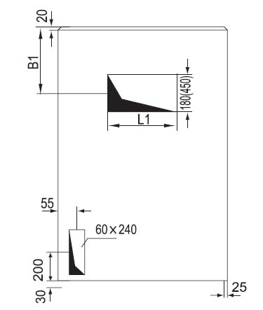
Dimension in brackets means dimension of heavy-current cubicle
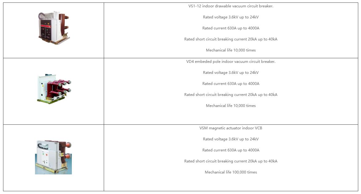
Main components charateristics
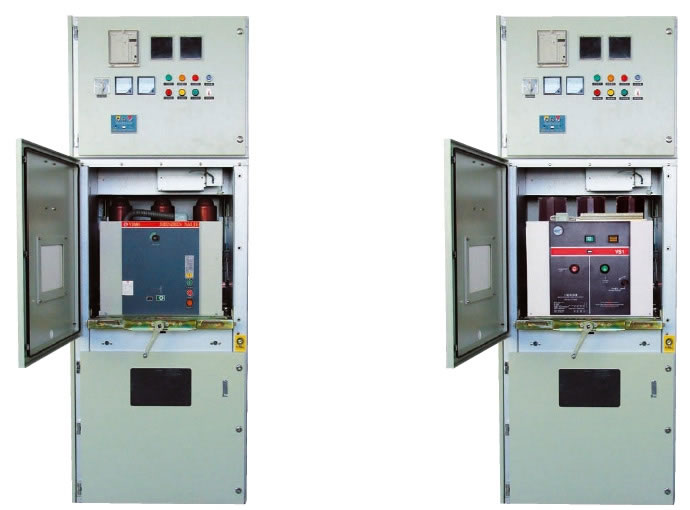
Photos of frontal view
Transportation, Maintenance and Order
Transportation and Storage
The switch cabinet can be transported by fork truck if guaranteed to be fixed on the bottom plate, and by handling or removing the entire entity if not fixed on bottom plate, but any case it should betransported vertically, no allowance for inversion in order not to damage the internal components. The switch cabinet(even for that with outer package) should not be exposed outside for storage for along time. The switch cabinet that needs the long-term storage should be put in the dry and ventilate indoor warehouse. The period of validity of outer package of switch cabinet is normally no more than 1year.
Maintenance
Free of maintenance for 3 years under the normal conditions.
There is no need of maintenance and any lubrication for the single-spring and dual-spring operation mechanism of load switch.
The relay protection device should be checked by the requirement of the manufacturer before put into the running.
The maintenance periodicity for ring main unit is normally one time every year.
Maintenance by the below requirement:
Fasten all the electrical connectors(main bus bar, switch, cable, measuring meter)required by Installation and Operation Instruction.
Clean all the parts by dust collector(main switch, auxiliary switch, tripping mechanism, motor etc.) and check the appearance.
Have a switching on/off operation for all switches including earth switch.
Turn on auxiliary control electric source not giving the remote control signal to have a electrical order operation.
Clean the busbar cubicle and cable cubicle.
Order
Complete-set Product:
The below documents are attached with the switch panel when out of factory;
Qualification Certificate of Product;
Installation and Operation Instruction;
Packing List;
Engineering Design Document of Product;
Accessory of switch panel :
one operating handle of load switch attached with each complete set;
The customer should offer the following information for order:
Wiring diagram of Main circuit Loop and Special Technical Requirement;
Installation Arrangement Plan of switch panel;
Specification of component inside switch panel and the schematic diagram of auxiliary loop and
control loop diagram.
Other written documents specially required.