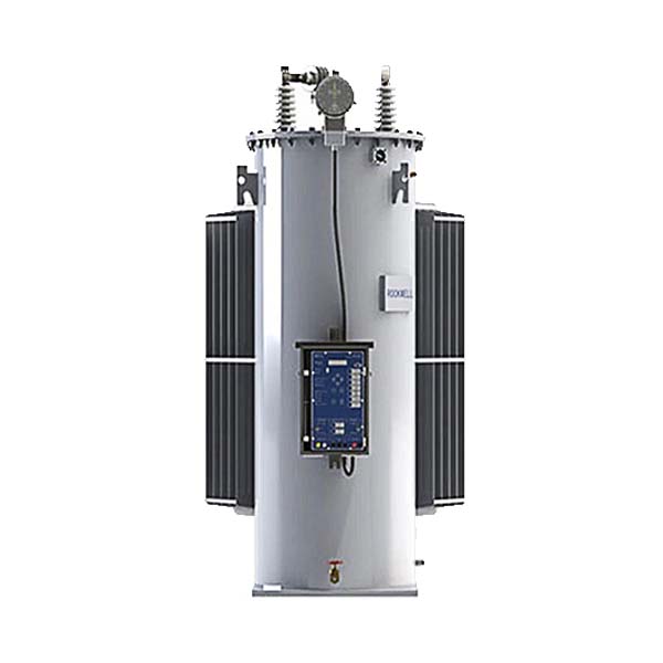
Single-phase automatic step voltage regulator
Description
Overhead line Auto Step voltage regulator
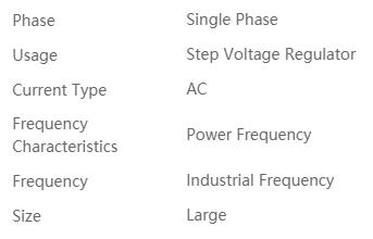
Single phase auto step voltage regualtor for up to 40.5kV system
32 steps voltage regulator
----------------------------------------------
>>> Weiguan Electric Co., Ltd. Company is the top leading manufacturer of single phase and three phase type AVR Step voltage regulator up to 40.5kV.
>>> Weiguan Electric Co., Ltd. Company is only one complete solutions provider of AVR Step voltage regulator in china.
>>> Weiguan Electric Co., Ltd. Company has own core technology of step voltage regualtor whole compoents like: Regulation control relay, On load quick-drive tap changer, Auto transformer, Current transformer and voltage transformer, Position indicator, etc.
----------------------------------------------
The RVR-1 type automatic step voltage regulator is actually a single phase oil immersed auto-transformer with RVR controller and gathering sampling of voltage and current signal, on load tap charger controlling device to achieve gird more efficient from adjust the load character by increase and decrease the voltage.
The RVR-1 type automatic step voltage regulator AVR is full typ tested Per ANSI C57.15 standard.
It is long life performance, over 1,000,000 times electrical and mechnical life operation.
>>> Voltage regulation
32 step of regulation in step of 5/8% for a total of 10% voltage boost to 10% voltage buck
>>> Voltage rating
For MV voltage 2.4kV (60 kV BIL) to 35kV (200 kV BIL) at 50/60HZ system
-----------------------------------------------
Weiguan Electric Co., Ltd. the top leading manufacturer of MV AVR - Autovoltage regulator
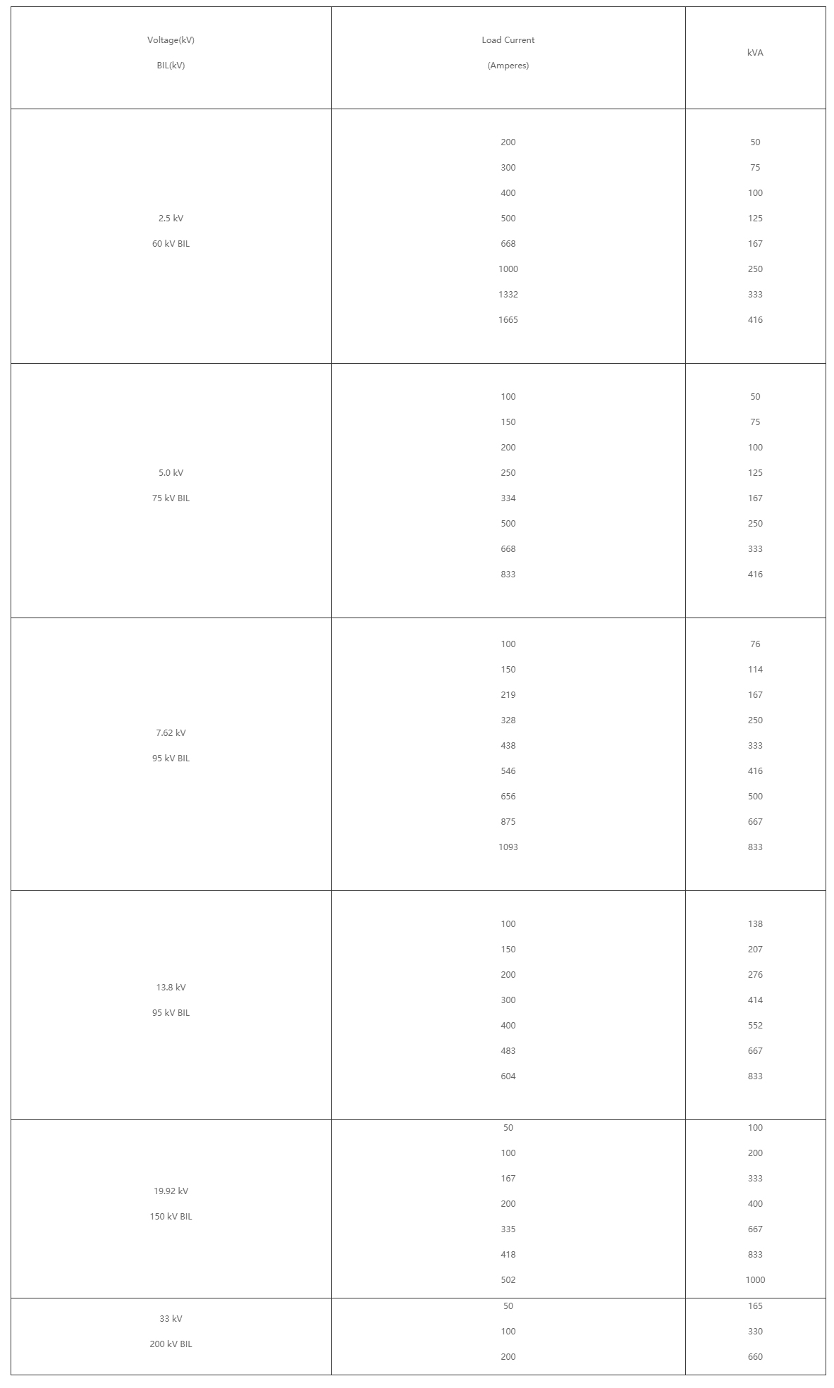
Technical data of single phase auto step voltage regulator
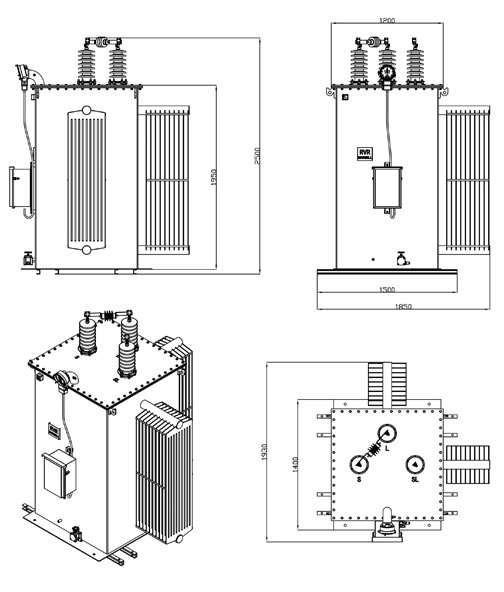
Overhead line AVR auto step voltage regulator dimension
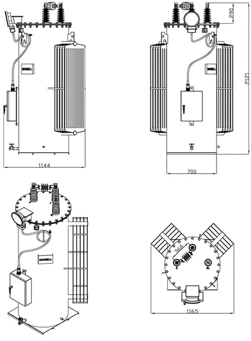
Substation type AVR auto voltage regualtor dimension
15kV,33kV Step voltage regulator Specification
EEU Standard of 15kV,33kV Step voltage regulator Specification
The step voltage regulators is complied with the latest editions of and amendments to, the standards/specifications listed below:
· IEC 60076-1 Power Transformers – General;
· IEC 60076-2 Temperature rise;
· IEC 60076-3 Insulation levels, dielectric tests and external clearances in air;
· IEC 60076-5 Ability to withstand short-circuit;
· IEC 60076-10 Determination of transformer and reactor sound level;
· IEC 60137 Insulated bushings for AC voltages above 1 kV;
· IEC 60296 Specification for unused mineral insulating oils for transformers and Switchgear;
· ASTM D202 Testing of Insulating Papers;
· IEEE C57.15 Requirements, terminology and test code for step-voltage regulators.
1.1 Types of Voltage Regulators
The step-voltage regulators is single-phase units with oil immersed copper or aluminium windings and on load tap-changing mechanisms.
They are suitable for pole mounting and shall be naturally cooled (ONAN).
The core material is Cold – Rolled Grain Oriented Silicon Steel (CRGO).
1.2 Performance Characteristics
1.2.1 Rating
The following ratings are covered by this Specification – 1MVA, 2MVA, 3MVA.
Voltage regulator MVA shall be calculated based on the following assumptions:
a) Continuous steady load.
b) Continuous ambient temperature of 300C.
c) ONAN cooling.
d) 55 K average winding temperature rise limit and 50 K top oil temperature rise limit.
e) Maximum winding hot spot temperature rise of 68 K.
The step voltage regulators will be capable of carrying the overloads as shown below without loss of normal life.
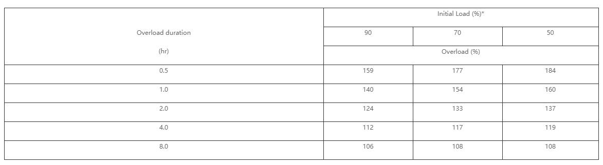
Note*: Initial load is defined as average load for 2 hours or 24 hours prior to overload, whichever is the greater.
The Contractor shall include test certificates indicating that these requirements are met.
1.2.2 Voltage Ratio and Tapping Range
The step voltage regulator shall be suitable for a nominal input system voltage of 33 kV or 15 kV as may be requested and shall be supplied with On-load Tap-changers rated 10% above and 10% below the nominal system voltage, plus or minus 16 steps in 0.625% increments. The tap-changing mechanism shall be motor driven quick break type and completely oil immersed.
1.2.3 Impedance
The impedance voltage shall not exceed 1% for all kVA ratings.
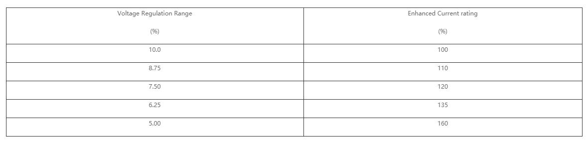
1.2.4 Enhanced Current Ratings
It shall be possible to supplement the throughput current rating of the voltage regulator by limiting the range of voltage regulation as shown in below.
1.2.5 Short Circuit Ratings
Voltage regulators shall be capable of withstanding without distress RMS symmetrical short circuits with the following system fault levels: The ability to achieve this shall be proven.
· System short-circuit levels:
a) 15 kV system: 650 MVA;
b) 33 kV system: 1800 MVA.
When calculations of winding mechanical stress are offered in place of a test, they shall be in accordance with latest CIGRE guidelines (e.g. Publication 209) and show appropriate safety margins.
· Duration of short circuit shall be 1 second.
· Initial average winding temperature shall be 105oC.
· Final average winding temperature shall be ≤ 250oC f
1.2.6 Losses
Load loss and no-load loss measurements shall be carried out in accordance with IEEE C.57.15, to include:
No-load loss is the average of no-load loss in the neutral and next adjacent boost position for step-voltage regulators that do not include a series transformer.
No-load loss is reported for neutral position, maximum boost position, and position adjacent-to-maximum boost position for step-voltage regulators that include a series transformer.
Load loss is the average load loss in both maximum and adjacent-to-maximum buck positions, and the maximum and adjacent-to-maximum boost positions (that is, 4 positions) with rated current in the windings.
The Contractor shall state the guaranteed losses subject to tolerances specified IEEE C57.15; the losses shall be valued on the following basis:
a) Core Loss - $4,800/kW
b) Winding Loss - $1,800/kW
Account will be taken of losses when evaluating the offer. The bid documents shall include all of the specified loss data listed in items 1. 2. and 3. above.
The Contractor shall also state the value of guaranteed magnetising current subject to tolerances specified in IEEE C57.15.
1.2.7 Insulation
Bushings and terminals shall be capable of withstanding the voltages applied during the winding tests. The bushing routine power frequency withstand test shall be 10% higher than the test voltage for the applicable winding.
1.2.8 Noise
The average noise level of the step voltage regulator shall not exceed 48 dB(A) when tested as per IEC 60076-10.
1.2.9 Radio Influence Voltage
The maximum Radio Influence Voltage shall be 250 micro volts, measured as specified in IEC 60437.
1.3 Controls
The step voltage regulator control panel shall be in a weather resistant enclosure with provision for locking with a padlock with 6 mm diameter hasp with 25 mm clearance.
The control panel shall be constructed as a single unit and be capable of being removed from the enclosure without disconnecting components or shall be capable of being disconnected from the control cable.
Control conductors shall be colour coded in accordance with IEC 60446 or labelled for easy identification.
Electronic components shall be hermetically sealed, identified, easily reached for testing and capable of operating in high ambient conditions.
The voltage regulator control panel shall be capable of being field calibrated and shall include the following control facilities:
a) Control Power Circuit Breaker.
b) Internal/External power source selector switch.
c) Off manual raise/lower automatic motor transfer switch.
d) Bandwidth adjustment from 1.5 V to 3.0 V on 120 V base and independent of voltage setting.
e) Voltage level adjustment – 105 V to 135 V in one volt increments.
f) Static time delay variable 10 secs. to 120 secs.
g) Position indicator drag hand reset button.
h) Neutral position indicator light.
i) Bandwidth position indicating meter.
j) Output voltage test terminals.
k) External voltage source terminals.
l) Six digit operation counter.
m) Current testing means.
Ten metres (10 m) of control cable shall be provided between the regulator and control box. The cable and controls shall be factory fitted to the regulator. The location of any plug on the cable shall be identified by the Contractor but should preferably be at or near the control panel.
Load side voltage transformers and current transformers shall be supplied with the regulator and mounted inside the tank. The voltage transformer ratio shall be 15000/110 or 33000/110 as appropriate. Current transformer rated secondary current shall be of the value that meets with the Employer's approval.
Interlocking shall be provided to prevent energisation of the high voltage bushings in the event of an external 120 V supply being applied to the control panel.
Control devices shall be to Accuracy Class 1.
1.4 Bushings and Terminals
1.4.1 Bushings
Voltage regulator bushings shall conform to IEC 60137. The whole of the lower end of bushings shall be below the oil level at 10oC. The bushings shall be of the outdoor weatherproof type.
Bushings shall be sufficiently robust to withstand transport risks and replacement shall not require removal of the voltage regulator top cover.
1.4.2 CreepageDistance
The minimum creepage distances shall be:
· 15 kV (Um = 17.5 kV) – 542 mm;
· 33 kV (Um = 36 kV) – 1120 mm.
1.4.3 Bushing Labels
The voltage regulator shall be fitted with three bushings to the top cover and shall be clearly engraved or marked `source', `load', and `common' or `S', `L', and `SL' or both.
1.5 Lightning Arresters
A total of 3 lightning arresters shall be fitted at the top of each regulator tank. One arrester shall be associated with each of the `source', `load', and `common' bushings. Any necessary bypass arresters should be factory fitted and connected across the series windings.
1.6 Grounding Terminals
All regulators shall be provided with a grounding terminal with a 10 mm diameter hole. The material shall be galvanised steel.
1.7 Tank Fabrication
Regulators shall be of the sealed tank type and the top cover shall be bolted to the main tank and sealed with a neoprene bonded cork gasket.
The regulator shall have a means of venting gases built up due to energised tap changing under oil.
The regulator shall be designed such that partial or complete un-tanking for inspection and maintenance may take place without disconnecting any internal electrical or mechanical connections.
The regulator shall be designed as pole mounted and shall be equipped with brackets for round pole mounting.
The minimum thickness of steel used shall be 3 mm.
1.7.1 Finish and Corrosion Protection
The regulator tank and its accessories shall be adequately protected against corrosion and the tender shall include a statement of the method protection proposed.
Hot dip galvanising or a stainless steel of a grade approved by the Employer is preferred. Where this is not practical the tanks shall be shot blasted and then immediately zinc sprayed to an average weight deposit of not less than 550 g/m², followed by a zinc chromate based primary paint, and two coats of durable oil and weather resisting paint. Finish colour shall be Admiralty Grey.
The inside of tanks shall be coated with oil resisting varnish or paint so that the oil cannot come into contact with the tank metal at any time.
1.8 Voltage Regulator Oil
Regulator shall be supplied with initial filling of Class 1 insulating oil conforming to IEC 60296.
1.9 Accessories and Fittings
The accessories and fittings with which the regulator is equipped shall include those listed in the following clauses:
· Oil gauge. This shall be of the sight gauge type and shall be used to indicate both oil colour and level.
· Draining valve shall be equipped with a non detachable handle and protecting plug and shall be located at the bottom of the tank. A filling pipe shall be located above the full oil level at the top of the tank.
· Step position indicator with upper and lower drag hands shall be inclined and easily readable from ground level.
· A voltage limit control shall be provided that prevents the regulator tapping beyond the maximum raise and lower positions.
· Pole mounting brackets/platforms shall be fitted to each regulator and details of same shall be supplied to the Employer at tender stage.
· The regulator tank shall be fitted with a spring operated self-healing pressure relief device. Operating pressures shall be consistent with tap changing pressures and tank pressures withstand.
· Rating and Connection Plate
Each regulator shall be fitted with a rating plate of weatherproof material showing the following items indelibly marked:
a) Type of regulator.
b) Specification to which manufactured.
c) Serial number.
d) Manufacturer's name.
e) Year of manufacture.
f) Number of phases.
g) Rated power.
h) Rated current.
i) Rated voltage.
j) Rated range of regulation.
k) Number of steps plus/minus.
l) Rated frequency (50 Hz.).
m) Impulse level full wave kV.
n) Volume of oil.
o) Total weight including oil.
p) Year of manufacture.
q) Employer's order no.
r) VT Ratio (33000/110 or 15000/110).
s) CT Ratio.
1.10 Testing and Inspection
1.10.1 Routine Tests
Routine tests shall be carried out on all regulators and shall be free of charge.
The tests shall be carried out in accordance with IEC 60076 where this is applicable. Since this class of equipment is not fully covered by IEC standards, some tests may require to be in accordance with IEEE C57.15. When this is necessary, it shall be clearly indicated in the bid documents.
The following routine tests shall be carried out:
a) Measurement of winding resistances.
b) Ratio and accuracy tests.
c) Polarity and Phase Rotation Tests.
d) Measurement of impedance and load loss at rated current and frequency.
e) Induced potential test.
f) Measurement of No-load loss and Excitation Current at rated voltage and frequency.
g) Manual and automatic operation with the regulator fully assembled and with internal voltage supply.
h) Leakage Test: The criterion of leakage shall be discolouration by oil of whitewash applied externally to suspected parts at an oil temperature of 90oC or other method approved by the Employer.
The results of these tests shall be recorded on a Routine Test Certificate, and two certified copies of this shall be sent to the Employer immediately after the tests. No regulator shall be dispatched until the Employer's written approval of the relevant Routine Test Certificate has been given.
Routine Test certificates shall include in addition to the test results:
a) Employer Order Number.
b) The Manufacturer's Serial Number.
1.10.2 Type Tests
Type tests shall be carried out on individual regulators at the Employer's request and shall be separately priced. They shall be witnessed by the Employer and/or his representative. Any particular unit or units may, at the Employer's discretion be chosen for testing.
The tests shall be carried out in accordance with the Standards specified.
The tests shall include any or all the tests listed below.
a) Temperature Rise Test as IEC 60076-2.
b) Impulse voltage withstand test including chopped waves as IEC 60076-3.
c) Noise level measurement per IEC 60076-10.
d) Bushings to be certified in accordance with IEC 60137 and include type tests for wet power frequency withstand and temperature rise test. Routine power frequency withstand tests on bushings shall be at least 10% greater than the maximum withstand level on the transformer.
e) Winding Insulation Test per ASTM D202, Clauses 92 97.
Type/Design Tests may (at the Employer's discretion) be dispensed with if the Contractor/Contractor furnishes evidence to the Employer's satisfaction that the relevant tests have already been performed on identical equipment. In this case the Contractor/Contractor shall provide documentary proof in the form of Certified Test Certificates that the assembled equipment and its component parts been successfully type tested by an independent testing authority in accordance with the relevant clauses of referenced Standards. Test Certificates as evidence of successful completion of type tests shall be submitted as part of the Bid.
Acceptable independent testing Authorities include the following: KEMA - Holland, CESI - Italy, EDF - France and IREQ, - Quebec, Canada. Approval of type tests certificates supplied by any other authority is subject to the written acceptance of Employer.

Address: NO.308 WEI 17 RD CENTER INDUSTRIAL PARK YUEQING CITY ZHEJIANG CHINA 325600
Tel: 0086-577-62667968
Phone: 0086-13868723687
E-mail:Sales@dist-transformer.com
Scan the code to browse the official website of the mobile phone


